Research and development departments within the Low and High Voltage Division
Research and development departments within the Low and High Voltage Division
The activity of low and high voltage research and development The work carried out within this division is fundamental to ensuring the quality and safety of energy equipment. Through its accredited laboratories, the division combines rigorous testing with technological innovation, offering complete solutions for the electrotechnical industry.
Objectives and Areas of Competence
1. Innovation in Testing and Diagnosis Methods
A constant priority is the achievement of research for the assimilation of new tests, measurements and diagnostic methods. This involves continuously updating procedures in accordance with changing international standards, as well as developing our own techniques for assessing the condition of equipment, in order to detect incipient defects and prevent breakdowns in electrical networks.
2. Multidisciplinary Applied Research
operate applied research aimed at determining the performance of electrical equipment in a wide range of areas:
- High Voltage: Insulation behavior under extreme electrical loads;
- Electromagnetic Compatibility (EMC): Operation of equipment without interference;
- Low Voltage: Operational safety and efficiency;
- Environmental Factors: Resistance to adverse climatic conditions (temperature, humidity, pollution).
3. New Product Development
The activity of research and development for the creation of new products and equipment aims for rapid technology transfer to production. We design and test innovative prototypes that meet the demands of the modern energy market, including solutions for Smart Grid and energy efficiency.
RENAR Accreditation and International Recognition
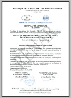
RENAR Accreditation Certificate (Click for PDF)
Official Documents
The low and high voltage testing laboratory for electrotechnical equipment is accredited by RENAULT (Romanian Accreditation Association), guaranteeing technical competence and impartiality of results according to the SR EN ISO/CEI 17025 standard.
-
➤
Accredited tests for the Low and High Voltage Testing Laboratory
-
➤
LOVAG Registered Laboratory
International recognition through the Low Voltage Agreement Group.
| Staff structure | |
|---|---|
| Scientific researcher, grade II | 2 |
| Scientific researcher, level III | 5 |
| Scientific researcher | 2 |
| Development Engineer Level II | 2 |
| Development Engineer | 2 |
| Auxiliary staff | 21 |
RESEARCH AND DEVELOPMENT IN THE FIELD OF HIGH VOLTAGE TECHNOLOGY
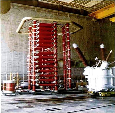
A. Lightning impulse and switching impulse voltage generation system
The pulse generator
- The pulse generator has the following technical characteristics:
- Umax = 4.2 MV, energy E = 336 kJ
Measuring equipment
- Capacitive divider 4.2 MV
- Digital impulse voltage measurement system type TR-AS 100-10/ 4
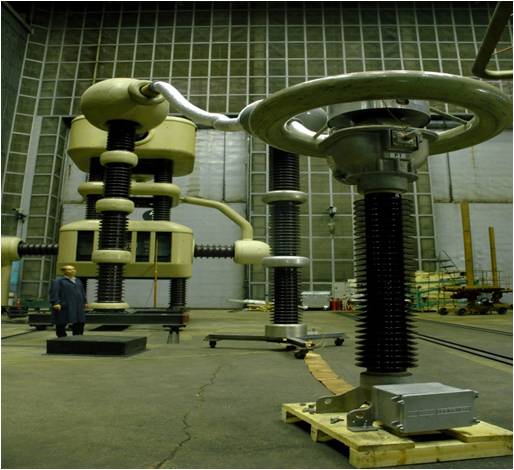
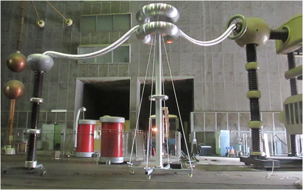
B. Alternating voltage system
1. Alternative voltage cascade 1.2 MV – 1.2 MVA
- The voltage cascade is made up of two identical transformers;
- Rated power 1200/900/750 – 680 kVA
- Maximum output voltage 1200 kV and 1 A
- The measurement system is a high voltage divider type WMC 160/1200
2. Test transformer 350 kV – 350 kVA
- The measurement system consists of: pressurized gas divider type MCF 75 300 kV
3. Test transformer 200 kV – 200 kVA
- 300 kV voltage divider
C. DC voltage system
Technical Features
Cascade rectifier (DC) with the following technical data:
- Nominal voltage 1 MV
- Rated current 30 mA
The measurement system consists of a 1 MV high-voltage resistive divider and a Keithley-type voltmeter.
D. The measurement system for tan δ capacitances
Equipment used for measuring capacitance and tan δ
1. High voltage bridge – Megger type used for on-site tests:
- Voltage: 250 V at 12 kV;
- Capacitance: 1 pF to 1.1 mF;
2. C+tgδ measurement system Tando-Omicron type
- tan δ: 0.1 % rdg. + 1 x 10⁻⁴ 5 μA ≤ IIN ≤ 1 A
- Capacitance: 0.1 % rdg. + 0.1 pF 5 μA ≤ IIN ≤ 1 A
The Research Laboratory provides scientific services for:
Power and Switching Equipment
- High power transformers
- Voltage and current measuring transformers
- Disconnectors and Switches
- Electric cells
- Encapsulated Rods and Reactors
Insulation, Protection and Cables
- Isolated crossings
- Insulating housings, ceramic, glass or composite insulators
- Lightning protection equipment (determination of initial advance time)
- Dielectric tests for medium voltage electrical cables
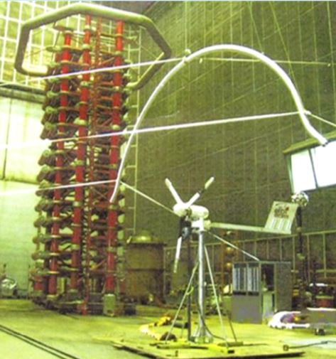
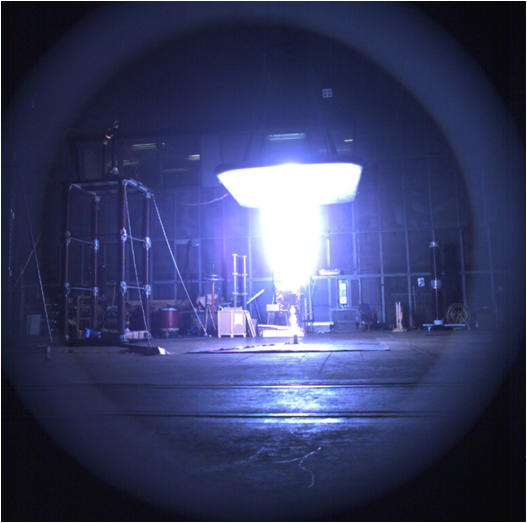
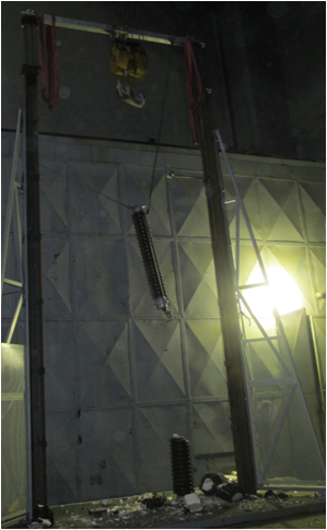
The impact of a lightning strike on the rotation of a wind turbine blade
Objectives and Object of Testing
- Development of protection against lightning strikes;
- Tested object: small wind turbine, scale 1:40, 3 MVA;
- The purpose of this test was to determine the effective protection of the wind turbine against lightning;
Methodology and Scientific Context
- Pulses (SI) with 250/2500 μs were applied;
- The climb and descent method was applied to determine the yield stress of 50%;
- The research was conducted at the request of the Faculty of Electrical Engineering at the University of Belgrade, as part of a doctoral thesis.
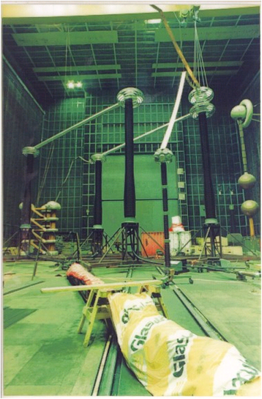
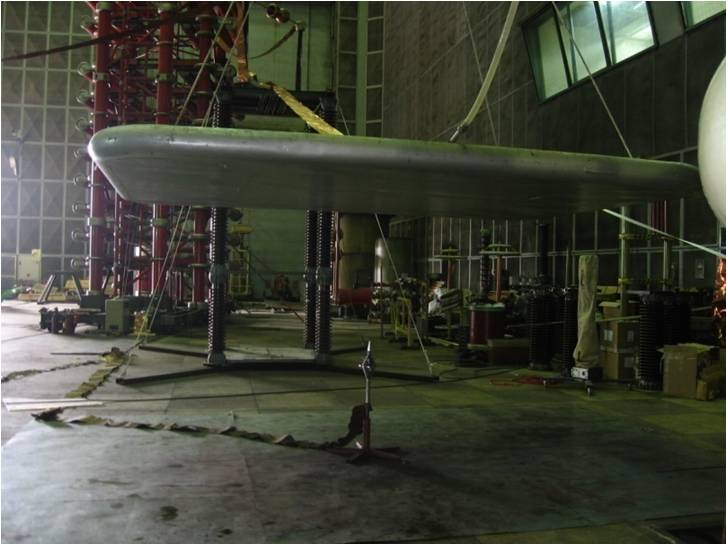
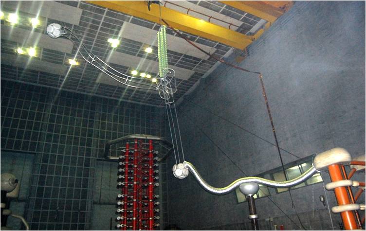
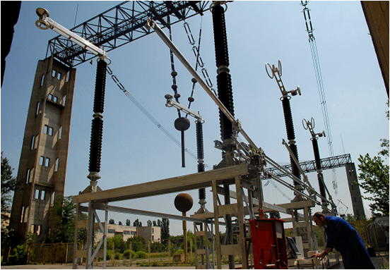
Lightning impulse protection – determination of the initiated advance time
The setup used for the research on determining the initiation lead time for lightning protection
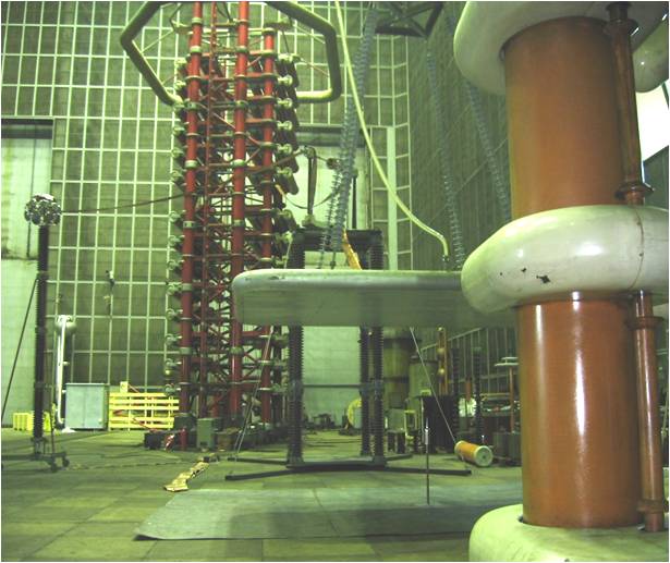
Lightning protection – determining the initiation time in advance
Description Methodology
- a continuous bias voltage is applied to the upper metal plane (simulates the cloud) and the lightning impulse wave is adjusted to obtain a contour;
- the maximum value (on lift) of the pulses and the trigger time are recorded for each pulse.
- The early emission lightning rod must be compared to a simple conductive rod.
- The tests are performed under the same conditions and configurations for each rod and lightning rod.
International Partners
The research was conducted for the following foreign partners: FOREND – Turkey; SCHIRTEC – Austria; PITTAS – Greece, QUALITY STRENGTH – Taiwan, ERICO – Netherlands, COSMOS – Russia, Tai Surge – Taiwan, etc.
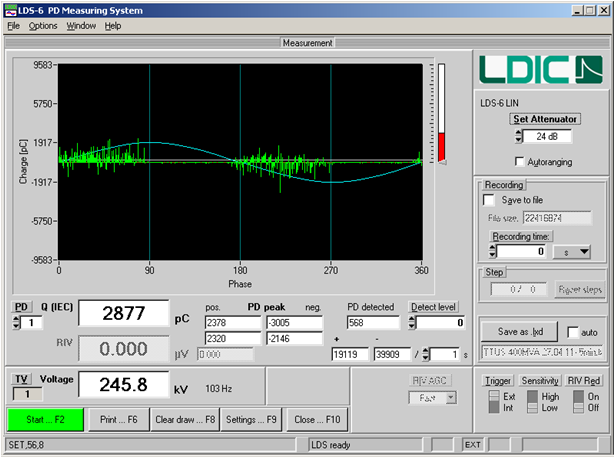
Partial discharge (PD) measurement
Partial discharge measurement systems:
1. LDS-6 type instrument
- Pulse processing (wideband): 100-400kHz
- Detectable apparent charge: 0.2pC-100000pC
2. MPD 600 type acquisition units
- For input frequency:
- V input-0Hz – 4.3 kHz
- PD-0Hz – 20MHz input
- Fiber optic cables: 3m, 20m, 100m
Partial discharge measurement in high voltage equipment:
- Power transformers (oil and dry)
- Current and voltage measuring transformers
- Isolated crossings
- Cables
- Capacitors
- Metal oxide arresters
Radio interference measurement (RIV)
RIV measurement system:
- Measurement impedance
- Electromagnetic interference receiver, type SMV 42
RIV measurement on high voltage equipment:
- Suspension and traction insulator chains
- Overhead line accessories, Support insulators
- Instrument transformers
- Switching equipment
The research was conducted for the following foreign partners:
Necks – Sweden, Gural – Turkey, ABB – Sweden, Efacec – Portugal, Hydro Quebec – Canada, Elimsan – Turkey, COELME – Italy
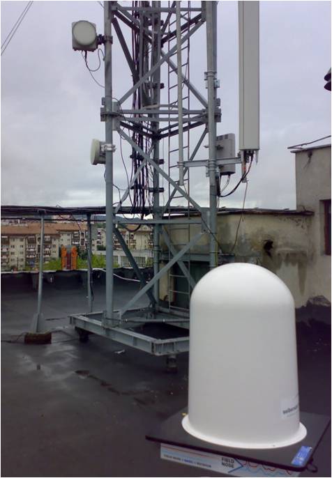
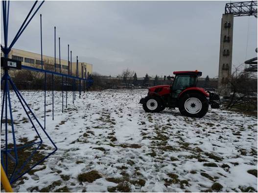
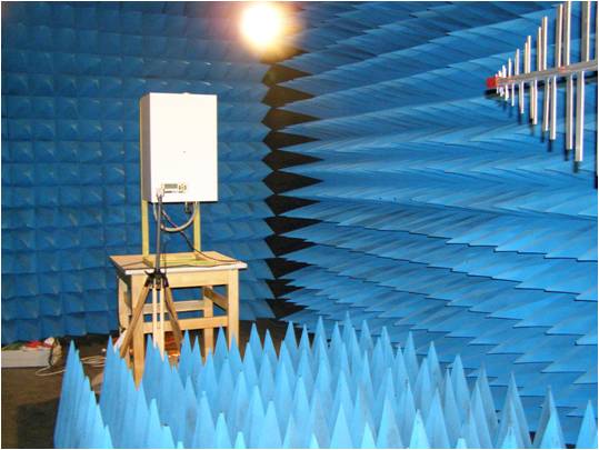
Research in the field of electromagnetic compatibility
Laboratory and field research
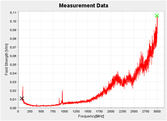
Measuring exposure of personnel/population to electromagnetic fields
- Electric and magnetic field measurement:
- – Electric and magnetic field: 5 Hz – 32 kHz
- – Electromagnetic field: 80 MHz – 3 GHz
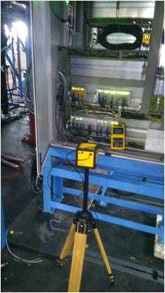
Comparison with the limit imposed by Directive 2013/35/EU (workers)
or WHO 1193/2016 (population)
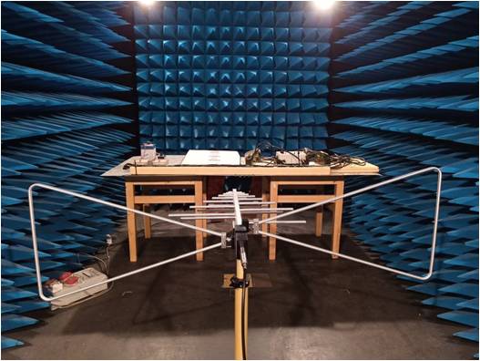
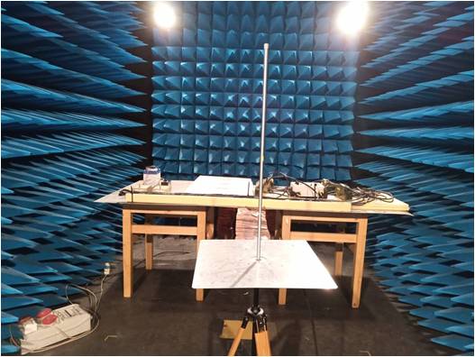
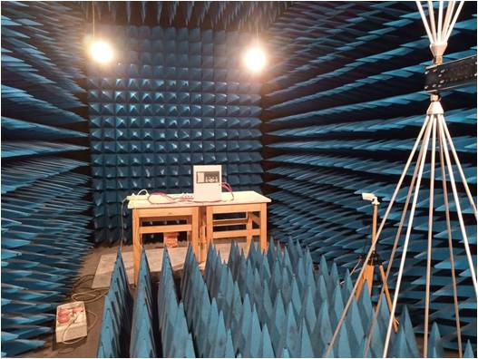
Measurement of conducted and radiated disturbances
Conducted and radiated disturbance measurement in the civil, automotive and military fields
Frequency range: 10 kHz – 18 GHz
Measurements according to:
- – EN 55011, EN 55014-1, EN 55025, EN 55032
- – Directive 2009/19/EC, ISO 11425
- – MIL-STD461G
Equipment used:
- Electromagnetic interference receiver: ESCI, SMV 42, PMM 9010/30P
- Artificial networks: LT 32/C, NNB 41, AN 2050, LN-KFZ/200, etc.
- Antennas: rod (VAMP 9243), frame (EMCO 6507, EMCO 6509), dipole (VHA 9103, VHA-9105), biconic (EFS 9218, UBAA 9114, VHBC 9133, VHBC 9124, precision PCD 8250), hybrid (logarithmic-periodic + biconic: BTA-M, HL 1000, VULB 9161), horn (DRH-18E), etc.
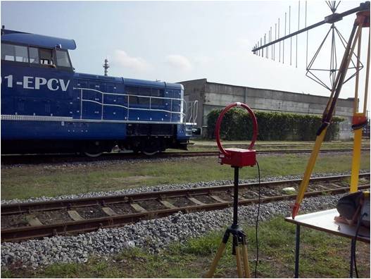
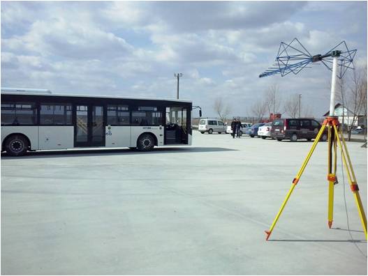
Measurement of radiated disturbances from vehicles
Frequency range: 10 kHz – 1 GHz
Measurements according to:
- – UNECE Regulation R10
- – EN 55025
- – EN 50121
Equipment used:
-
Electromagnetic interference receiver:
ESCI, SMV 42, PMM 9010/30P -
Antennas:
– frame (EMCO 6507)
– hybrid (logarithmic-periodic + biconical BTA-M)
Immunity tests to radiated radiofrequency electromagnetic fields
Frequency range: 80 MHz – 1 GHz
Severity level: up to 10 V/m (AM modulation, 1kHz, 80%)
Measurements according to:
- – EN 61000-4-3
Equipment used:
- Signal generator: R&S SML 03 (9 kHz – 3.3 GHz)
- Power amplifier: AR 250W1000A (80 MHz – 1000 MHz, 250 W)
- Transmitting antenna: Log-periodic (AT 1080)
- Field probe: HI-6005
- Software: EMC 32
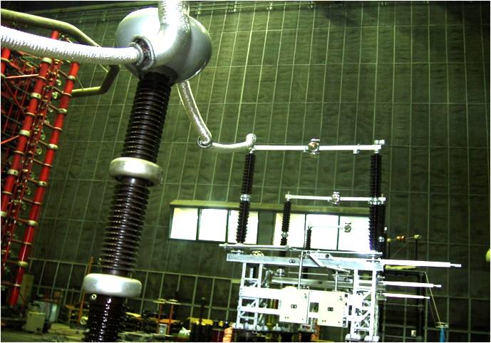
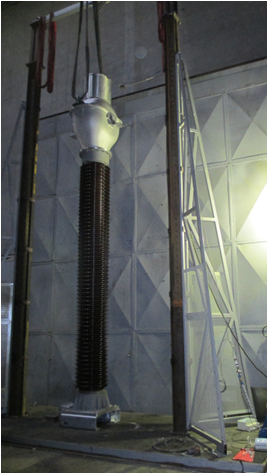
Research on the behavior of electrical power equipment under mechanical loads
Research on the mechanical endurance of separators with Um = 550 kV
Behavior of 750 kV support insulators under mechanical bending and breaking loads
Behavior of instrument transformers Um=550 kV under the action of mechanical forces
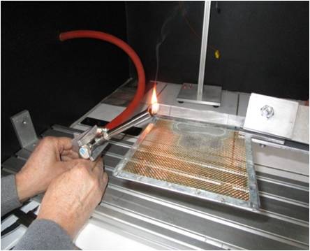
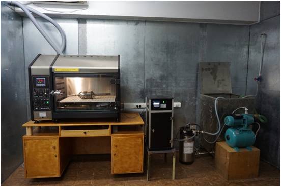
Research on the fire risks of electrical insulating materials
Horizontal or vertical flame tests
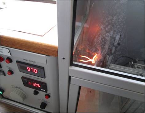
Glow wire tests
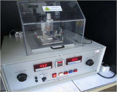
Ball pressing tests
Determination of youngness indices and resistance to the formation of conductive paths
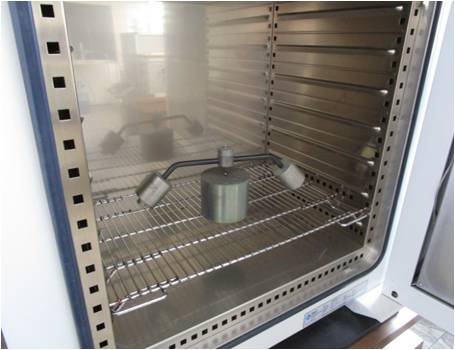
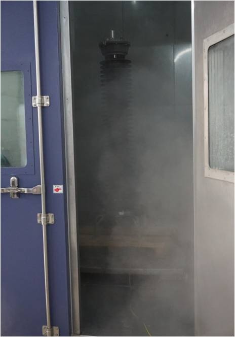
Research on the behavior of electrotechnical equipment under the action of environmental factors
Cold, dry heat, humid heat, temperature variations
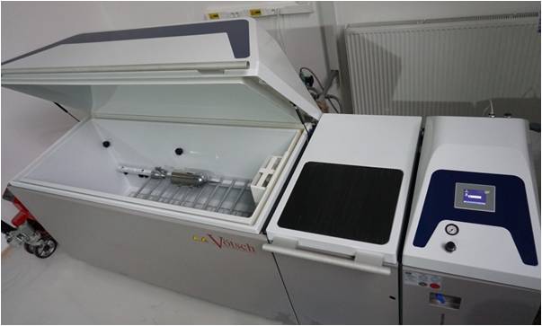
Salt fog
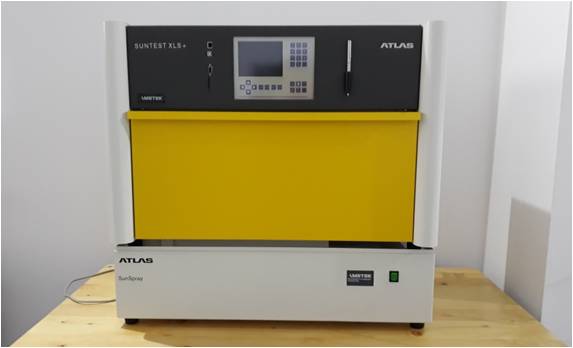
Ultraviolet radiation
Humid sulfurous atmosphere
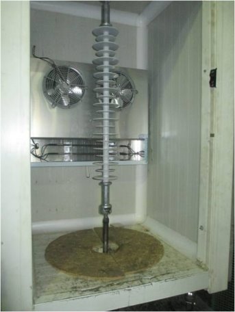
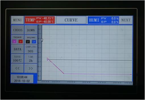
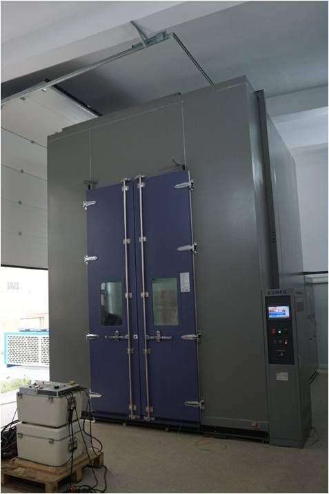
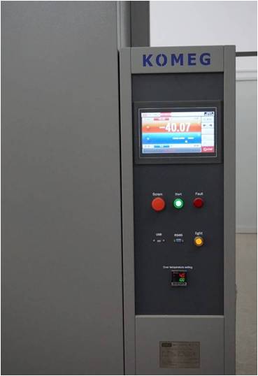
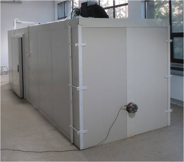
Research on the combined medium-voltage behavior of high-voltage electrical equipment
Climatic chamber
- Temperature range: -50°C … +90°C
- Relative humidity range: 15% … 95%
- Dimensions: 3m x 3m x 4m
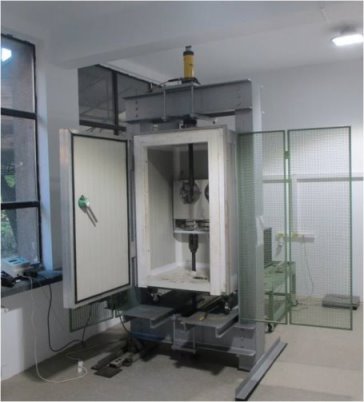
Research on the behavior of electrotechnical equipment under the action of mechanical factors
Compression-buckling
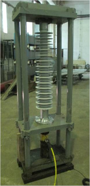
Temperature and tensile stress
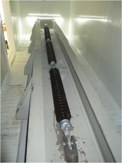
Research on the behavior of electrotechnical equipment under thermomechanical loads
Evaluation of the structural and electrical integrity of equipment simultaneously subjected to temperature variations and mechanical stresses (traction/compression).